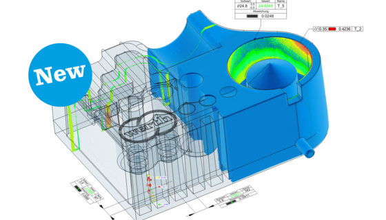
The definition of the tolerance structures, especially regarding the reference systems, should be coordinated between the manufacturer and the customer from the beginning. The main advantage of this second inspection procedure is function-related measurement. The output is easy to survey and provided in a graphic form. This enables operators who have not received any special training to operate the system.

Similarly, the tool correction used when inserting new tools can also be supported by the BestFit software. The selection of the system technology suitable for this measuring task must be based on the drawing tolerances of the profiles to be checked. Tolerances ranging from several tens of micrometers to maximally 0.1 mm are the rule. As a result, measuring uncertainties of 5 µm to 10 µm are often sufficient. However, this applies only to general distance dimensions and diameters.

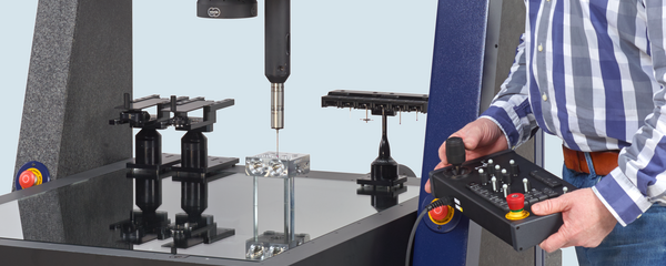
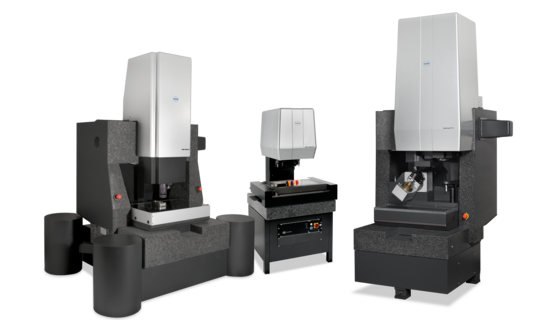
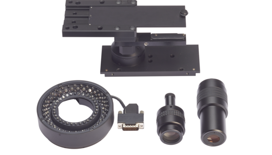
Since the measuring task is two-dimensional, optical measurement with image processing can be performed quickly. It is important to deburr the parts. Any remaining burrs are, however, suppressed by suitable image processing filters. The most user-friendly option is a device which allows the profile sections being measured to be placed on a glass plate (Fig. 60). No time-consuming refocusing is therefore required. Below the glass plate is a camera which can be moved in two coordinate directions and which is focused on the glass plate. The transmitted-light source is located above the workpiece. Since it takes only several tens of seconds to measure a complete profile, the manufacturing process is not held up for any length of time.