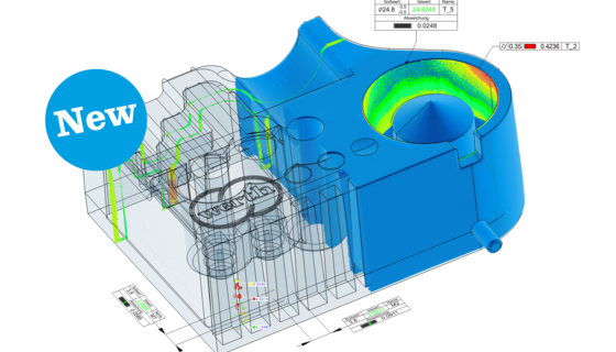
Beam hardening is not considered in the mathematical principle of X-ray tomography.  The measurement errors that result from this are known as beam hardening artifacts.  Their magnitude depends on the material and geometry of the measured object. Beam hardening can make measurements impossible in extreme cases. The boundary points between air and the material can no longer be correctly determined. In less extreme cases measurement errors still occur.  The image on the left shows the effects of beam hardening when measuring a light alloy casting.  The radiation spectrum can be changed by filtering the X-rays after they exit the X-ray tube.  Depending on the filter material used and the filter thickness, the low frequency portion of the radiation is attenuated. This high pass filtering is also known as beam hardening. The remaining high frequency radiation, which is therefore high in energy as well, is “hardened” only by a relatively small amount as it passes through the object and the resulting artifacts are less prominent. In addition, or as an alternative, the level of beam hardening can be determined for the material to be measured and can be corrected mathematically. The real penetrated length of a calibrated material sample, or of the work- piece itself, is related to the attenuation value determined by a test measurement. This is repeated for different lengths. This allows a characteristic curve to be calculated, showing the dependency of the attenuation coefficients on the penetrated length for the material to be measured.  This characteristic curve is used for correction in the subsequent measurements (b).  Note that the correction curve determined in this manner only applies for the material used in the test. It is also affected by the tube voltage and thus also by the frequency spectrum of X-rays and potentially by any beam hardening filters that may be used. In modern coordinate measuring machines with X-ray tomography, this correction is implemented with a simple additional measurement, from which the correction curve is automatically derived. Detailed explanation of this process, known as Empirical Artifact Correction (EAC), is beyond the scope of this work. To optimize the precision during measurement using this approach, it is necessary that the work piece is always positioned in the same orientation. Errors due to other physical effects  are partially corrected as well.  The use of Autocorrection is recommended in order to achieve maximum precision.