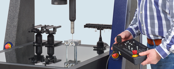
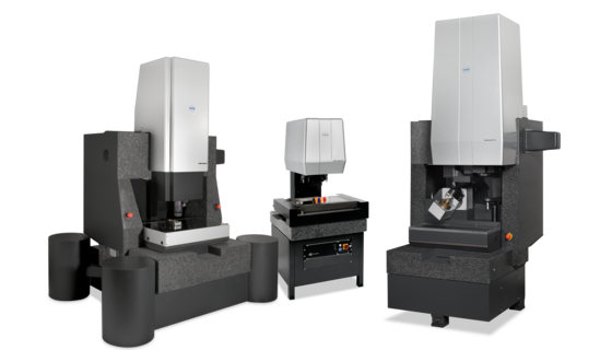
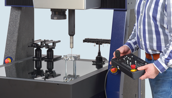
For higher precision requirements and larger measuring ranges, the mechanical guide way of the desktop model is replaced by systems with air bearings.  The high-precision guide ways are typically made of a natural hard stone material like granite.  All moving components glide along these surfaces on an air cushion of only a few micrometers to minimize friction.  The forces required to move the carriages are relatively small, and the lack of hysteresis in the positioning system results in low measuring uncertainties.

Moving-bridge coordinate measuring machines embody the principle of design now most often used in larger machines.  The bridge and its uprights or columns move along the primary (usually X) axis.  A carriage moves laterally on the bridge along the secondary (usually Y) axis.  The third (usually Z axis or ram) is attached to this carriage (Fig. 5c).  Since the sample is not normally moved during measurement, extremely heavy workpieces can usually be analyzed.  However, this superimposed arrangement of the moving axes often prevents the use of complex sensor configurations.  This configuration also makes it quite difficult to install the high-quality transmitted-light illumination systems required for coordinate measuring machines utilizing image processing.  For this reason, moving bridge machines are normally equipped with tactile sensors.

On stationary or fixed-bridge coordinate measuring machines, the object is moved along the primary axis while on top of a moving workpiece table.  The other two axes are arranged on the bridge (Fig. 5d).  The chief advantages of this design are that the drive systems and scales of all three axes can be mounted centrally (minimizing Abbe offset effects) and that its high stiffness minimizes rigid body effects and ensures low measuring uncertainties.  In addition, this design facilitates the integration of transmitted-light illumination systems and is especially advantageous for optical and multisensory coordinate metrology.  The high stability of this design also makes it possible to attach multiple sensors to a single ram.  Collision problems resulting from the use of multiple sensors can be prevented by using additional rams.  Sensor change is then performed by simply retracting and extending the corresponding rams as required.  The use of A and B (rotating and tilting) axes enables the dimensional measurement of complex parts without reclamping the workpiece.  One special construction type featuring a fixed bridge for smaller measuring ranges is the L-shaped structure (Fig. 5b)