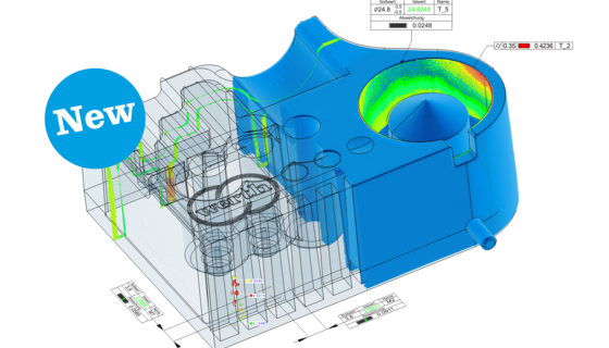
It is more effective to set up measurement sequences using 3D CAD data. By simply selecting the CAD patches that describe the areas of interest (e.g. a cylinder or plane), the corresponding measurement points are selected automatically. There are two basic methods available here. The first method, selection of a CAD patch, captures all the measurement points that are geometrically associated with that patch, considering border distances and exclusion zones (fenced off areas). The shape of the appropriate element is thereby completely captured with the maxi- mum number of points. As an alternative, a predefined point distribution tool can be used on the selected CAD patch using the standard procedure of tactile measurements. Measurement points are then generated only at these predefined locations and are used to calculate the geometric elements. The advantage of this method is the ability to directly compare the results with tactile single point measurements. However, the disadvantages of the low point density must be accepted. This second method is therefore suitable only for work pieces with little form deviation. The measurement sequences thus generated can be run automatically for repeated measurements of parts of the same type. One advantage of X-ray tomography is the possibility to analyze the measurement results independently of the measurement of the work piece itself, either with the measuring machine computer or with a separate offline workstation. In the latter case, the measuring machine can be used to measure the next work piece while the analysis of the previous one is performed. This is particularly useful if the calculation time for the analysis would occupy the measuring machine for an unacceptably long time. The total measurement time can thus be reduced by using offline stations. To further optimize the total measurement time, the measurement programs can be created offline in advance, similar to classic coordinate measuring machines. The CAD model is used again for this.
The tomographically captured measurement points are replaced by mathematically simulated measurement points based on the model. Programming can be done in the same manner as with the actual measured data. A side effect is that the dimensional accuracy of the CAD model can be checked prior to manufacturing the parts. Particularly for complex parts with many dimensions, this approach allows the measuring programs to be created before the work piece is even produced. The first article inspection can be done quickly. The time required for validation of a multicavity injection mold, for example, is thus reduced from the previous level of several days or weeks to just a few hours, even for a large number of cavities.
Seen in image above: Complete measurement versus simulated tactile measurement: a) Patch selection method b) Measurement using point distribution tools measurement error due to under sampling.