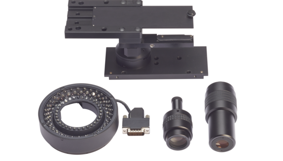
Figure 1: Laser sensor using the Foucault principle integrated into an image processing sensor (illumination systems not shown).
Optical Sensor Technology in Coordinate Metrology
In coordinate measuring technology, mainly tactile and optical sensors and X-ray computed tomography are used. Optical sensors differ in their functional principle and structure consisting of mechanics, optics, electronics, and software, and thus in their characteristics, whose basic understanding is helpful for the optimal application. Fragile workpieces, and those with small features, can also be measured non-contact.
An essential distinguishing criterion for the sensors is the physical principle of the transmission of the primary signal. In the series of papers “Sensor Technology in Coordinate Metrology,” first optical, then tactile sensors, and finally X-ray computed tomography are presented with their respective fields of application.
Optical sensors act like the eye in the measuring microscope, either perpendicular to the optical axis in the object plane (lateral sensors – image processing) or along the optical axis when focusing (axial sensors – distance sensors). In order to be able to carry out a 3D measurement of workpieces with optical sensors, a combination of both sensor types is required. With optical sensors, many measuring points are acquired very quickly or even simultaneously. Compared to other sensors, their use therefore usually leads to much shorter measuring times. For this reason, they are used for a wide range of workpieces in production control.
Flexible application possibilities for image processing
The image processing sensor images the measuring object through a lens onto a matrix camera. The camera electronics convert the optical signals into a digital image, which is used to calculate the measuring points in a computer with the appropriate image processing software.
In contour image processing, contours are extracted by suitable mathematical algorithms. This makes it possible to detect and filter out disturbing influences during measurement (contour filter). Many three-dimensional measurement tasks can be solved by combining image processing and focus variation techniques using the same sensor hardware. The determination of the dimensions of plastic parts, as well as the geometry of sealing grooves and plug cavities, is a main field of application.
Fast laser distance sensors
In Foucault laser sensors such as the Werth Laser Probe, a laser beam is “cut off” by a Foucault edge in the beam path and is imaged onto the object at the triangulation angle determined by the lens aperture. The signal evaluation is performed, for example, via differential photodiodes (Figure 1). In practical use, such a Foucault laser sensor is preferably integrated into the beam path of an image processing sensor. Thus it is possible to switch between both sensors without mechanical movement.
Several hundred to thousand points can be measured per second. This sensor is accordingly used for contour measurement on workpiece surfaces or, for example, also for flatness measurement.
Chromatic focus sensors for different surfaces

the distances between the object and the measurement head.
The optics of chromatic focus sensors (point sensor Chromatic Focus Point and line sensor Chromatic Focus Line) are designed in such a way that the different working distances are particularly pronounced for different colors of light (color length error). The best focused color of light has the strongest intensity at the measuring point. This intensity is determined with an integrated spectrometer and the corresponding distance value is assigned to the detected color (Fig. 2). The application possibilities for chromatic sensors correspond in principle to those of the Foucault sensor. However, the measurement of surfaces is possible for both diffusely reflecting and shiny surfaces, since direct reflection does not interfere.
The arrangement of a series of optical fibers allows the realization of the same principle as a line sensor. These sensors combine a high measuring speed with low measuring uncertainty.
Measuring surface topographies with focus variation
Focus variation sensors use the same hardware as image processing. When moving the sensor along the optical axis, a sharp image is generated for an image section in only one position. The contrast is used as a parameter for the sharpness of an image. From this the sensor position and thus the position of the point on the surface is determined.
If the procedure is performed simultaneously for each pixel of the camera, a large number of measuring points are obtained as a point cloud within a few seconds. This method (e.g. Werth 3D-Patch) enables a particularly simple and fast three-dimensional acquisition of surface topographies on workpieces made of various materials.
High precision confocal area sensors
A confocal surface sensor, for example the Werth Nano Focus Probe, projects light onto the object via an imaging system with pinholes. If the projected light spots are defocused by moving the sensor head, the light spots on the object become darker. Therefore, when the sensor head is moved relative to the object, an intensity curve is created. The maximum of the intensity curve represents the location of the object surface.
Due to the intensity evaluation, confocal area sensors, in contrast to focus variation sensors, can also measure reflecting surfaces, for example, regardless of the contrast of the workpiece surfaces. Applications include the measurement of stamping tools or coin embossing punches.