The numerical evaluation of scanned contours or surfaces is basically limited to regular geometric features such as cylinders, planes, straight lines, spheres and circles. However, modern methods of production increasingly permit the manufacture of free forms for which regular shapes no longer can be taken into consideration. Free-form parts are created whose form is described only by the CAD model.

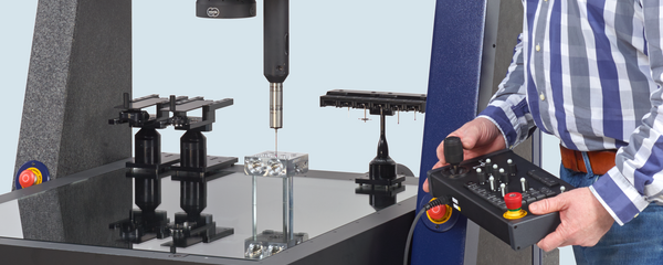
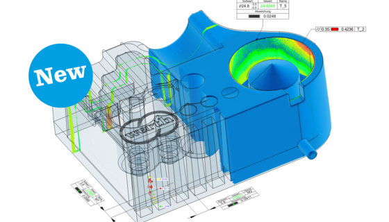
The areas of interest on the object are measured via scanning. Then, measuring software modules compare the measured values with the CAD model in off-line mode. Another possibility is to link the CAD software module directly to the measuring machine: In this case, the areas of interest are first selected on the CAD model and then automatically measured using the selected sensor mechanism. The results are documented either by graphic comparison or via graphic display of the deviations from the CAD model (Fig. 49).

The colors of the measured points underscore the deviation between the nominal and the actual shape. Four classes can be distinguished here: “positive in tolerance”, “negative in tolerance”, “positive out of tolerance” and “negative out of tolerance”. The amount of the deviation is indicated by the color. The possibility of changing sensors allows measurement of the entire surface of a part, even in cases where complex forms are involved. By integrating rotating axes in the measuring system, various different views can be included in the measurement and the part can be measured from all sides. Depending on the job requirement involved, the measured results can be displayed either in a previously qualified reference coordinate system (for example, in vehicle coordinates in the automotive industry), or in a coordinate system which has been optimally fitted into selected surface areas. The location of the measured points is optimized here in relation to the CAD model in such a way that the deviations are kept as small as possible.