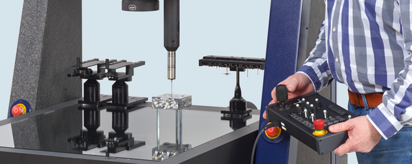
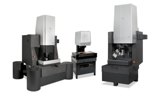
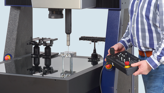
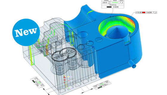
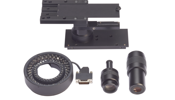
The sensors are selected directly via the user interface of the multisensor coordinate measuring machine. Among other things, the software takes the distance between the sensors into account. This distance is determined by qualifying a calibrated standard (reference sphere). The prerequisite for this is that the standard is in a fixed position which can be reached by all of the sensors used. Following the qualification procedure, the various sensors can be combined and used within a measuring run (for example, to “capture” the location of a bore via optical measurement and then measure the axial direction and form of the bore with a stylus). Another possibility is to perform tactile measurement of the spatial location of parts, align the workpiece coordinate system, and then optically measure small, complicated features (Fig. 47). The set-up times between sensors are thus omitted completely and the entire measurement job can be processed without reclamping the workpiece.

The programming of complex measuring runs is supported by the corresponding tools featured in the WinWerth® measuring software. Especially useful is the Feature Tree, which displays the measurement plan, and the organization of the measurement program in a treeshaped structure. By simply clicking a specific feature, the operator can determine the geometric elements that the feature is made up of. Further clicking leads step by step to the individual measuring operation and its corresponding technological parameters (stylus and illumination). Parallel to the feature tree, the corresponding features, geometric elements and measured results are also visualized in the drawing display of the measuring run and in the numerical measurement record. Logic operations can be programmed either in the feature tree or in the graphic view. A test and editing mode which can be used to process programs step by step and add to or edit the program in the learning mode can also be controlled via the feature tree.

A large number of measured points are required to measure form and position deviations. This is the only way to determine the actual form and, based on this result, perform further evaluations. The measured points are acquired via scanning. This is possible only with a measuring probing system and a Foucault laser sensor. Touch trigger probing systems also basically offer this function; however, they require longer measuring times to execute it. During scanning with an image processing system, several images are automatically combined to form a single overall contour while a contour is traced by the probing system. The size of such contours is limited only by the measuring range of the coordinate measuring machine used for scanning. They can be evaluated with respect to their size, shape and position. A determination of the positional tolerance based on the generally applied Gaussian associated elements does not always yield the correct result. For this reason, the positional tolerance must often be calculated by directly applying the minimum circumscribed/maximum inscribed circle methods (Chebyshev approximation). This is automatically ensured by the measuring software.