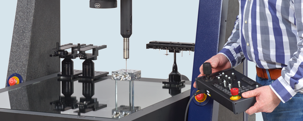
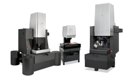
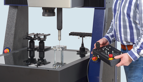
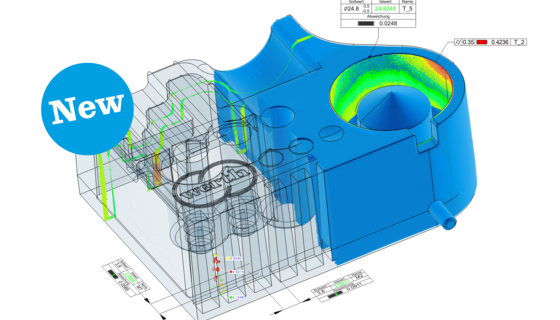
The injection molding process makes it possible to manufacture very complex plastic parts of good quality. Examples of such parts include functional and housing parts for automotive components, electronic and medical equipment and general consumer goods. A general trend toward miniaturization can be recognized in connection with parts of this type. The materials spectrum ranges from relatively hard plastics for housing parts to soft plastics with rubber-like properties. The production areas of injection molding plants are often highly automated and operated in four shifts. It therefore makes sense to automate the inspection process as well by integrating robots and pallet systems in four-shift operation in the production process (Fig. 57).

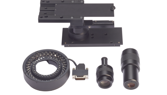
One key aspect regarding the use of measuring machines in plastics processing is the final inspection of products. Functional dimensions such as the distance of detents, sealing grooves and connector latches with tolerances of only several tens of micrometers and less are checked. Tactile measuring processes are often ruled out in such cases due to the large dimensions of the stylus tips and the excessive probing forces involved. For this reason, optical measurement is often the only possible way to check dimensional accuracy. A combination of image processing and autofocus sensor technology is used here. Problems are often caused by forms typical for plastic parts including mold release slopes and rounded-off corners. Depending on the color involved, sufficient contrast is sometimes difficult to achieve. An optimally flexible illuminating system is therefore a precondition for successfully measuring such workpieces with optical sensors. Bright-field/reflected-light illumination featuring adjustable-angle reflected light (like the Werth MultiRing®) provides a good basis. The Werth 3D-Patch or Foucault Laser Sensor function can also be used to ensure that rounded corners are measured reliably. The functional dimensions are evaluated according to ISO standards. Form and position tolerances often occur.

Housing and soft trim parts used in vehicles usually have surfaces designed primarily along aesthetic lines. The tolerances of these relatively inexactly defined free-form (or designer) surfaces usually lie between 50 µm and 100 µm. The measured values are compared with the CAD data point by point. The required large number of measured points can be acquired, for example, with laser distance sensors or 3-D sensors. If a 3-D multisensor coordinate measuring machine is combined with a rotational axis, complex plastic parts can be measured within a coordinate system from all sides, thus enabling complete inspection of the workpiece.

The second main area of application in the injection molding process is the measurement of injection molding tools and the erosion electrodes required to manufacture them. Due to the current trend favoring shorter product cycle times, it is becoming increasingly important to perform these inspections before beginning production. Once the injection molding process has been started, any subsequent correction would take too much time. Due to shrinkage and other influences of the injection molding process, the tool dimensions often do not agree exactly with the parts dimensions. Moreover, a much higher accuracy is required. A part tolerance of several tens of micrometers and a tool tolerance of several micrometers typically result in maximum measuring uncertainty requirements as low as 1 µm and less for the coordinate measuring machines used (according to the tolerance chain argument).

Tactile measurement is usually possible due to the stability of the metal materials used. However, it often proves inadequate where small dimensions are involved. Combination systems featuring touch trigger or (better yet) measuring probing systems, fiber probes and laser sensors are therefore used. Where complex injection molding processes are involved, it is advisable to measure production-related deviations from the CAD model in the scanning mode. The CAD model for the tool is intentionally modified either by the corresponding software functions or manually to compensate for process influences. The modified CAD model can then be used either to manufacture electrodes or to directly control the machine tools for tool correction.

In connection with the inspection of parts and the process-internal measurements described above, a general distinction must be made between two basic methods of workpiece alignment:

  • In the case of functional parts, the workpiece is often uniquely aligned with respect to the functional surfaces. Any free-form surfaces the workpiece may have are then checked within this coordinate system.
  • If any deviations are measured which are out of tolerance, it must then be determined whether the reference surfaces are incorrect or the free-form surface itself has a fault. The latter possibility can be checked by performing a 3-D best-fit of the free-form surface in the CAD model followed by a graphic evaluation. It is then also possible to change only the reference surfaces in the tool and thus avoid costly reworking of the free-form surfaces..