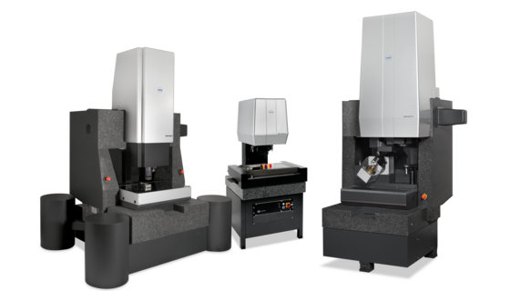
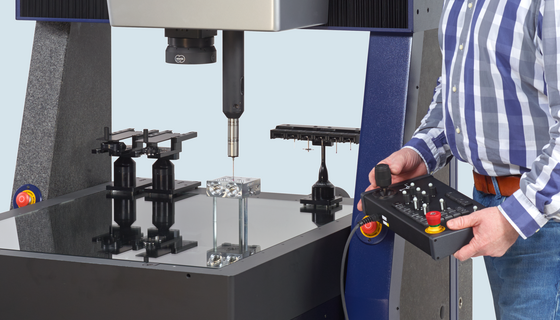
Plate bending parts are widely manufactured for PC boards and plug contacts in the electrical engineering and automotive industries. A two-dimensional part with cut-outs is the classical application for 100% optical coordinate measuring machines such as the profile projector. Due to the thinness of the material being measured, tactile probing would be difficult. Moreover, optical measurement is also faster and in line with workshop requirements. Since the optical sensor never touches or displaces the sheet metal part, the difficult clamping of small, resilient parts can be omitted.

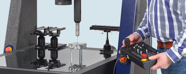
Today even complex, three-dimensional parts manufactured by modern punching and bending processes and multi-impression dies can be satisfactorily checked by multisensor technology. The outer contours of the objects are measured via image processing using both transmitted and reflected light. High-performance image processing with the corresponding filtering techniques is required for typical metal surfaces. Spatial distances can be measured using the autofocus or laser distance sensor. The use of styli is often unavoidable when measuring certain spatial dimensions and undercuts. Parts which spring due to their form must be measured with the fiber probe to minimize probing forces. Pallets for inspecting larger samples in automatic measuring runs are an ideal means of clamping such workpieces.

Sheet metal car body parts can also be measured with multisensor coordinate measuring machines. Optical sensor technology is obviously the best choice here in light of the faster measuring speeds attainable. As was the case with plastic parts, a combination of 3-D sensors and contact styli permits exact measurement of functional dimensions and multipoint measurement of free-form surfaces in a single clamping action. Linear drives enable rapid measurement to satisfy the demands of a manufacturing environment. Several features per second can be measured on a single part.
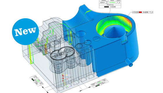
The scanning technique is suitable for complete inspections of two-dimensional sheet metal parts. Using the image processing sensor, the entire contour of a part can be measured quickly and automatically and then compared with the CAD data using the BestFit or ToleranceFit® software. The scanning technique is also suitable for checking punching tools. Both blanking punches and matrices can be measured directly on the cutting edge. The ToleranceFit® software enables graphic checking of the tool for the required size. Where high precision requirements exist, errors of procedure must be corrected (for example via wire EDM). The basis for doing this is provided by a BestFit comparison. The deviations between the nominal and the actual values are superimposed over the nominal contour with the opposite operational sign. The CAD file thus changed is then reused in the manufacturing process on the wire EDM machine to correct the geometric deviations of the punching machine (Fig. 58).

Since CAD tool data is normally available, measurements of functional dimensions can also be programmed very effectively using the software functions found in Werth Cad-Online® and Werth Cad-Offline®.