The most important attribute of a coordinate measuring machine is its contribution to the measuring uncertainty attainable in a measuring process. The user must be able to compare different machines, define their conditions of purchase and check their performance. The ISO 10360 standards have defined specifications and methods for checking these factors. However, these standards currently apply only to tactile sensors. The integration of optical sensors is based on the same fundamental principles and is currently in preparation. The verification of coordinate measuring machines basically concentrates on two parameters: the probing error and the length measuring error.

The inspection of the probing error has the purpose of characterizing the behavior of the sensors used and the repeatability of a measurement. This is done by measuring a calibrated sphere with a specified number of probing points and then determining a limiting value (probing error) from the range of the individual points around the sphere as an associated element. Special considerations regarding the testing of optical sensors will be dealt with in the German VDI/VDE Directives 2617, Series 6.

The chief factors limiting the performance of mechanical styli are the stylus sphere or tip itself, the bending of the stylus shaft, and nonlinearities or hysteresis on reversal in the probe. For optical sensors, these factors include the resolution of the sensors, the optical magnification of the lens systems, the depth of field when measuring with the autofocus and, with laser sensors, the radiant reflectance of the material surface as well. Influences caused by the machine itself primarily result from the resolution of its scales and its vibration behavior. While the sphere can be probed bidirectionally from all sides with tactile sensors, only unidirectional probing is possible with many optical sensors. A two-axis indexing probe head which also requires checking must then be used to enable bidirectional probing.

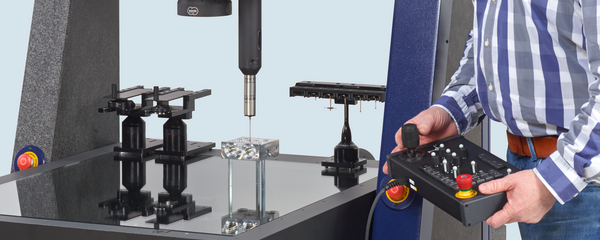
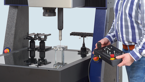
The length measuring error takes several factors into account. These include the probing behavior of the sensor, the length-dependent measuring error resulting from the mechanical guideway errors, the software geometry correction and the length-dependent measuring error resulting from the thermal behavior. It is checked according to ISO 10360-2 by measuring lengths on parallel or step gages (Fig. 53).

Measurement of the gage blocks is possible with all tactile sensors and with the Werth Fiber Probe as well. When checking the length measuring error with other optical sensors, a similar procedure is followed; however, different standards are used. For measurement with an image processing system, the gage blocks are replaced by glass scales with vacuum-deposited chrome graduation lines. Measurement is performed similar to the way in which this is done with a step gage. The required bidirectional probing of gage blocks is not possible with one-dimensional and multi-dimensional distance sensors. In this case, ball plates or ball bars must be used. However, in order to ensure the comparability to tactile measurements performed on gage blocks, a mathematical correction must be performed when using this method of measurement. This takes into account the fact that a sensor calibration error (caused by, for example, incorrect probe sphere diameter, incorrect origin of laser coordinates, or incorrect magnification) influences the measured result when measuring the gage blocks but not when measuring the sphere. At the same time, the averaging effect achieved by probing the sphere with a large number of measured points is corrected in the result.

The machine specification largely depends on the sensor system used. Therefore, during all acceptance tests, the user should ensure that the sensor system specified in the data sheet is actually used. If the sensor system actually used differs from the one specified, an additional increase in the measuring uncertainty can be expected. The next section will deal with this in more detail..