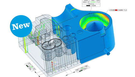
Many CAD systems now offer the option of integrating PMI data (Product and Manufacturing Information). The resulting CAD data sets contain, in addition to geometric descriptions of the CAD elements, the dimensioning provided by the design engineer, including tolerances and datum elements. This information now forms an ideal framework for the creation of a measurement sequence using the WinWerth® measurement software. By clicking on the desired geometrical characteristic, all geometrical features needed for the measurement are color coded. For measuring with the automatic scan path and point distribution, the user can click on the geometrical elements one after the other, and if required, modify the probing strategy, as well as measure immediately in the CAD-Online® mode. After the measuring has been completed, the nominal values and tolerances can be transferred directly from the PMI data into the measurement report and modified manually. By overlaying the CAD model, PMI color coding and the display of the elements that have already been measured, additional work steps can be recognized easily. With PMI, the tolerated elements can be identified at a glance. Searching for the datum elements in the drawing is no longer required. This simplifies the interpretation of the task at hand and minimizes transmission errors at the same time.
NEWS
Werth Knowing
Copyright © 2023 | Werth Inc | (860) 399-2445 | 8 Custom Drive, Old Saybrook, CT 06475