Starting with the DIN EN ISO 10360 international series of standards, the Association of German Engineers (Verein Deutscher Ingenieure: VDI) has developed a guideline for acceptance testing of coordinate measuring machines with X-ray tomography.
This has been integrated both in the VDI/VDE 2617 series of guidelines, which handle coordinate measuring technology in general, and in the VDI/VDE 2630 series, which specifically addresses X-ray tomography. Based on the existing standards for tactile and optical coordinate measuring machines, the parameters of probing error and length measurement error are defined therein. The probing error quantifies the three-dimensional error behavior of the coordinate measuring machine in conjunction with the X-ray tomography sensor in a small portion of the measurement volume. It is derived by measuring a calibrated sphere standard with at least two magnification settings that differ sufficiently from each other and calculating a sphere from 25 measurement points for each magnification. The dimensional error, PS, and form error, PF, are differentiated. The derived sphere diameter is used to check the parameter MPE (maximum permissible error) of the machine specification for PS, the dispersion of the measured points is used to check the parameter MPE for PF (range of radial errors). To ensure comparable results, the material and dimension of the sphere must be pro- vided as a side condition of the specification. This also applies to the magnification, the associated measurement volume and the permissible environmental conditions, such as temperature and temperature gradient. The parameters that are set by the user in normal measuring operation should also be provided, such as: the X-ray voltage, the measurement time, the use of physical or mathematical filters, artifact correction methods and the use of additional sensors for artifact correction. It is important that the operating parameters used are similar to those that would be used in the normal operation of the coordinate measuring machine. If the manufacturer does not provide any quantifiers in the specification, then these parameters can be freely selected by the user.
This ensures that the manufacturer is required to indicate any limitations in the product specifications. The specification and testing of probing error can be done differently for different operating modes, such as measurement “in the image”, measurement “at the image” (raster tomography), or with spiral tomography. Because mathematical filtering methods can improve the results of the probing error determination, but also reduce the resolution, the spatial (structural) resolution should also be specified. The test procedure for it should be indicated as well. This provides the user the ability to determine whether the small features on the measurement objects can be accurately measured and if the machine meets the specified probing error under identical operating conditions. The spatial resolution can be checked by measuring suitable test objects. It is largely determined by the physical properties of the X-ray sensor (focal spot diameter, rotary axis behavior and pixel size) and the analysis software. For example, a small sphere or an arrangement of spheres can be measured with diameters so small that they can just barely be measured.
The length measurement error E and its specification parameter MPE E describe the three-dimensional error behavior of the coordinate measuring machine over the entire measurement volume. In addition to the larger influence of the mechanical components of the coordinate measuring machine, the temperature and the quality of the temperature compensation show up here as particularly significant influences. In principle, the length measurement error can be checked for coordinate measuring gage blocks, following the classic approach for tactile machines. However, when selecting the test standard, care must be taken that the maximum potential X-ray penetration length of the material is not exceeded. This may not be possible under certain circumstances when gage blocks made of steel, ceramic, or other material are used. Alternatively, it is suggested that lower density test bodies be used with length dimensions incorporated in the form of embedded spheres or one dimensional arrays of one or more spheres.
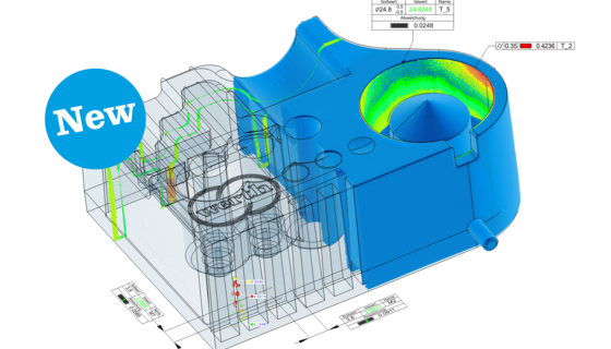
Seen in image above: Determining the probing error (P) of a tomography coordinate measuring machine using a sphere measurement. The numerical values indicated are based on analysis of 25 probing points conforming to ISO. The analysis of approximately 20,000 measurement points is included in the diagram.