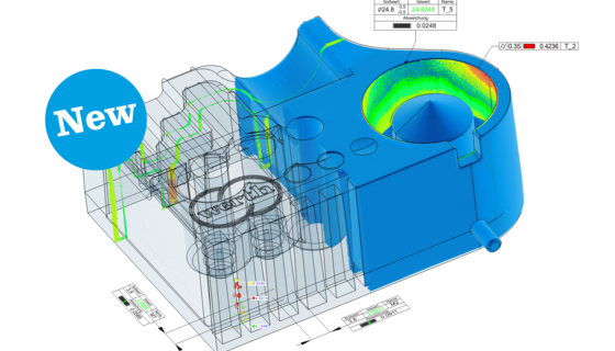
Several different methods are used to achieve high product quality in injection molding. The standard method is to design the mold under consideration of the production parameters, for example the shrinkage of the plastic can be taken into account. An alternative method uses modification of the production parameters based on simulation processes (for example a mold flow analysis). Despite such complex simulations the required product quality is not always reached. Further improvements can be attained by iterative modification of the molds. Currently many iterations and experienced operators are necessary, resulting in high costs. The goal is full automatic mold correction which is directly connected with metrology in order to reduce correction loops.

The mold correction consists of three sub-processes: the design of the mold, the injection molding process and the quality control of the workpieces and / or molds. All three areas are tightly connected. Both the molds and the production parameters directly influence the quality of the workpiece. The workpiece measurement data defines the process quality which then influences the correction process.

This process begins with the design and production of a mold based on the nominal geometry of the workpiece. The first produced workpiece is measured using computed tomography. Modern systems can very quickly generate a high resolution point cloud. The difference between the measured geometry and the nominal geometry is calculated using the measurement results. These are mirrored around the nominal geometry. Afterwards a new corrected CAD surface is generated using the mirrored measurement points. Complicated manual methods to correct surfaces are not necessary. Errors resulting from the operator are almost eliminated. This guarantees the high quality of the CAD model and results in a fast correction process.