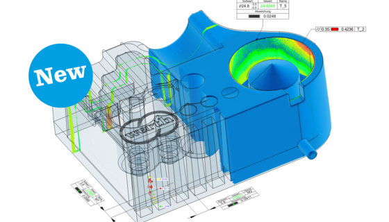
With FormCorrect, the exact work piece geometry is achieved by a mostly automatic correction of the CAD model. The deviations between the original CAD model and the test work piece measurement data are directly determined by the WinWerth® measurement software and mirrored at the CAD model surface. Using this data WinWerth® generates a corrected CAD model, with which systematic manufacturing deviations are compensated. On this basis, a preview of the remaining deviations of a corrected work piece is now possible. Extensive reverse engineering, which requires expert qualifications, is no longer needed. The geometric changes can be realized both in the work piece CAD model and in the mold CAD model. Using the corrected work piece CAD model, a new simulation of the manufacturing process is performed, and a data set for the work piece rework is generated. The simulation parameters used here are the same ones used in the creation of the first sample work piece. Due to its high precision, FormCorrect often requires only one corrective iteration, which in turn results in a significant reduction in development process costs. Through the integration into WinWerth®, the changes to the CAD model can be realized on the basis of the standard alignment process. The coordinate systems can, for example, be set via reference elements either with the help of multi-point alignment (MPA) or by using a Gaussian adjustment. With this, FormCorrect can be used with a variety of application specific alignments, which correspond to the functional and manufacturing related specifications. The option of a largely fully automated correction process reduces operator influence and increases user friendliness. The result is a corrected CAD model that is compatible with practically all existing CAD/CAM systems. The implementation of new CAD/CAM software is no longer necessary. In contrast to common reverse engineering, the application is now much simpler. Based on a color-coded deviation depiction between nominal and actual, the user can simply click on the areas that are to be corrected in the CAD model. FormCorrect is able to calculate individual surfaces that are mathematically unlimited or limited by curved edges. The transitions between different surfaces can be automatically calculated now, and the corrected surfaces can be adjusted into the entire CAD model. Measurement data is the basis of FormCorrect. This data is best generated using Werth TomoScope machines to capture the work pieces geometry. Through the use of X-ray tomography, the entire work piece can be captured, and the CAD model can be corrected using this information. The high measurement point density enables high-resolution correction. The high precision and traceability of the measurements ensure excellent product quality that is achieved with a reasonable investment of time and effort.
Seen in image above: The functional principle (left) and WinWerth® FormCorrect results: a) deviation between measuring data generated using a Werth TomoScope® and the work piece CAD model, b) deviations mirrored at the surface of the work piece CAD model, c) automatically determined grid points to calculate the corrected surface, d) deviations of the corrected surface to the original work piece CAD model, this is equivalent to the corrections of the mold, e) remaining deviations after correction of the mold CAD model, modification of the mold and new manufacturing.