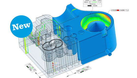
If the neighbor points of a given measurement point are required for further processing, they are identified directly by the triangle definition. No time-consuming search algorithms are needed. If the entire amount of object information is not required, the calculation can be limited to individual surface points. This can be done, for example, by simulating the function of a tactile coordinate measuring machine. However, this leads to a loss of information about the work piece.  To  derive dimensions  from  these  measurement  points,  groups  of  points  are  consolidated into geometric elements such as lines, circles, cylinders, or planes, as is usual in coordinate metrology. This can be accomplished by manual selection of the measurement points or in a more user friendly manner by applying a CAD model. Thus the measured object is first overlaid on the corresponding CAD model. This is done automatically using suitable algorithms.  The regions of interest of the point cloud are then selected by clicking on the corresponding CAD patches. The correct measurement points are then captured automatically by the software. The actual dimensions are calculated from the geometric parameters of these elements (e.g. distance between two planes, or between centers of circles) and compared to the nominal values.

See in above image determination of dimensions, the measurement point cloud is overlaid on the transparent CAD model  a) Four patches are selected  b) A first plane is calculated  c) Four more patches are selected d) A second plane is calculated, and the planes are used to calculate a distance.