• Home
learn more

Glossary C

Terms relating to coordinate metrology with optics, probe, computed tomography and multi-sensor systems

CNC coordinate measuring machine

CNC measuring machine

CT

Simplifying for coordinate measuring system with computed tomography

CT coordinate measuring machine

Calibration

During the inspection of a coordinate measuring machine within the scope of the acceptance test for the customer or the machine maintenance, the measurement errors to the calibration value of standards are determined according to DIN EN ISO 10360 and the guideline VDI/VDE 2617. For a calibration, the specification of the measurement uncertainty is necessary. To ensure that a check or calibration is carried out in accordance with the standard, the manufacturer or calibration laboratory should have a certificate from the national accreditation body DAkkS.

Compact coordinate measuring system

Computedtomography and multi-sensor compact instruments provide an economical entry into coordinate metrology. The basis for the TomoScope® XS machines is the new tube design resulting from intensive development work and intelligent design solutions. For the first time, computed tomography coordinate measuring machines with standard-compliant specifications could be offered at about the same price level as conventional tactile or multi-sensor coordinate measuring machines.

Complete measurement

Computed tomography

Simplifying coordinate measuring system with computed tomography

Computed tomography coordinate measuring system

Computed tomography measurement

CT measurement is a complete and non-destructive measurement. The workpiece is irradiated by X-rays in various rotational positions and a virtual workpiece volume is reconstructed from the recorded 2D images. This can be used for non-destructive testing, e.g. according to the BDG P201, P202 or P203 guidelines, and the analysis of assemblies. According to the calculation of the measuring point cloud, all geometrical characteristics can be determined and 3D nominal-actual comparisons can be carried out. Development costs are reduced by minimising initial sampling times. Mold corrections using the CAD model for mould making and additive manufacturing are also possible directly in the WinWerth® measurement software.

Confocal sensor

By moving the probe head relative to the workpiece, the intensity of the light points is varied by defocusing. Based on the intensity curve, the position of the workpiece surface is determined.

Coordinate measurement

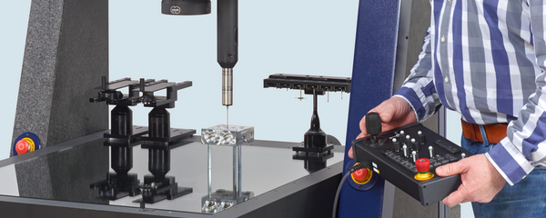
Coordinate measuring machine

Coordinate measuring machine with image processing

Coordinate measuring machine that realises two-dimensional measurements of workpieces by capturing images with the help of imaging optics, a digital camera and image processing software. By using focus variation techniques or autofocus with the same hardware, 3D measurements are also possible. Often form the basis for multi-sensor coordinate measuring machines.

Coordinate measuring software

The measurement software is used to control the coordinate measuring system, qualify the sensors, determine the size, shape and position using the measurement points and create a measurement report.

Coordinate measuring system

Coordinate measuring machines are used to determine geometrical characteristics of workpieces such as size, mould and position. The principle is based on the determination and subsequent mathematical evaluation of the spatial coordinates of individual points of the workpiece geometry. Coordinate measuring systems are subdivided and designated according to the operating principle of the measuring point recording or method of primary signal transmission. The term coordinate measuring system deliberately also includes non-conventional methods (photogrammetry, computed tomography); the conventional term coordinate measuring machine has traditionally been used more for machines with tactile and optical sensors that can be positioned relative to the measuring object with the aid of coordinate axes. Coordinate measuring machines have one or more sensors (see also multi-sensor coordinate measuring machines).

Coordinate measuring system with CT

Coordinate measuring system with computed tomography

With these machines, the primary signal transmission takes place according to the principle of X-ray computed tomography. In order to scan a workpiece tomographically, several hundred two-dimensional radiographic images are taken in succession at different rotational positions of the measuring object. For this purpose, the object is placed on a rotary table, which is rotated successively or continuously. The three-dimensional information about the measuring object contained in this sequence of images is extracted by suitable mathematical methods and made available as a reconstructed workpiece volume. Similar to two-dimensional image processing, the measurement points are calculated from the volume data using suitable methods. Alternatively, the volume data can also be used for visual inspection, e.g. for voids, inclusions or other properties of internal geometries.

Coordinate measuring system with image processing

Coordinate metrology

Coordinate measuring systems and associated methods which serve to determine and subsequently mathematically evaluate the spatial coordinates of individual points, as well as their development and application

chromatic sensor

Depending on the distance of the object to be measured from the sensor, the exit surface of the optical fibre imaged by the lens is best focused on the object for a particular colour. The best focused light colour has the strongest intensity at the measurement point. This is determined with an integrated spectrometer and the corresponding distance value is assigned to the detected colour.

Contact
Select another country or region to see content in your language.